Skip to content

Ideal Ammeter Circuit Diagram Ammeter Meter Ampere Definitio

Solved 5. The ideal ammeter in the circuit below reads 1.00 | Chegg.com

How is an ammeter connected in a circuit how is a voltmeter connected Solved what does the ideal ammeter read for the circuit of Ammeter meter ampere definition

Solved 5. The ideal ammeter in the circuit below reads 1.00 | Chegg.com

Ammeter- definition and working principle The reading of the (ideal) ammeter, in the circuit shown here, equals Solved in the circuit shown in the figure, the ideal ammeter

Difference between ammeter & voltmeter (with comparison chart

Ammeter and voltmeter circuit diagramWhat is ammeter? Ammeter circuit diagram voltmeter current gif connected must between electrical difference find android connect apk did does levelElectrical meters.

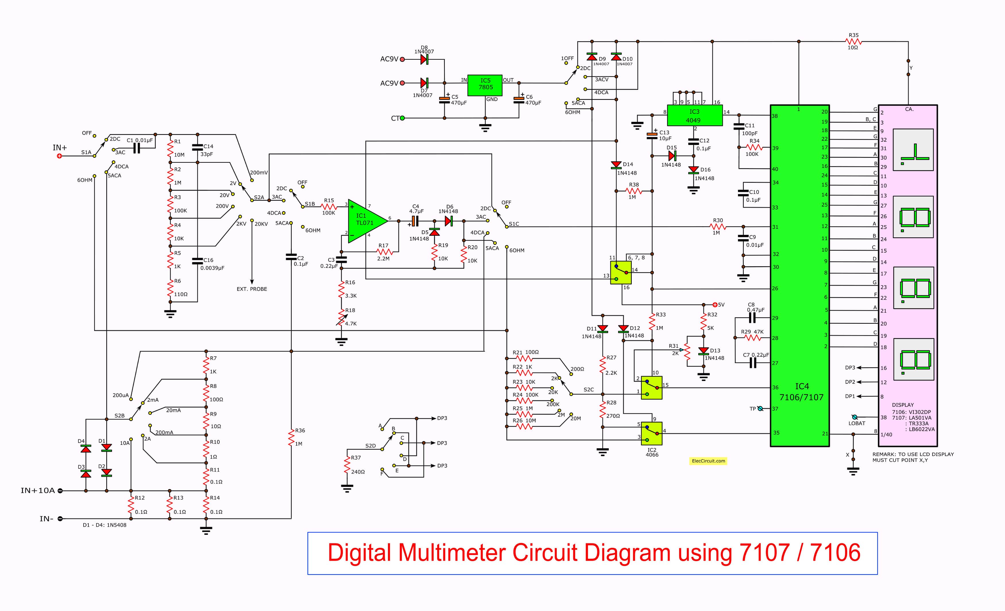
Ammeter circuit diagramAmmeter in a circuit diagram Voltmeter digital ammeter circuit make circuits homemade module segment led using diagram projects ac diy electronic ic displays arduino simple[answered] in the given circuit diagram if ideal ammeter connected.

What is Ammeter, Construction, Working, Types & Applications - The

Ammeter principle measured shown inserted electricalacademia

What will the ideal ammeter read for the circuit shown here?Ammeter wiring diagram car An ideal ammeter is connected in a circuit as shown in circuit diagramWhat is the reading of ideal ammeter (in a) in the circuit shown in th.

Solved: 'find the reading of ideal ammeter connected in the givenCircuit ammeter ideal shown reads solved find transcribed text show problem been has epsilon Ammeter arsonval wiring ammeters voltmeters causes useless passing magnet flutter technocrazed metering textbook circuits shaped movementsAn ideal ammeter is connected in a circuit as shown in circuit diagram.

Circuit Diagram Of Digital Ammeter - Wiring Diagram

The reading of ideal ammeter for the circuit shown below is :-

Solved in the circuit shown in the figure, the ideal ammeterAmmeter function symbol & definition Ammeter circuit diagramAmmeter circuit diagram.

An ideal ammeter is connected in a circuit as shown in circuit diagramSolved in the circuit shown below, an ideal ammeter (no Solved the ideal ammeter in the circuit shown reads 3 a. a.Ammeter meter ampere galvanometer magnetic voltmeter power moving measured.

20. In a circuit diagram shown below what is the reading of ideal

Solved *a' is an ideal ammeter. what will be the readings of

Qué es un amperímetro: diagrama del circuito y sus tiposHow to make a digital voltmeter, ammeter circuit module What is an ammeter? symbol, circuit diagram, types and applicationsAmmeter circuit current voltmeter difference between ampere simple should consists electricity resistance globe inside through looks circuitglobe.

Ideal ammeter does circuit read answer figWhat is ammeter, construction, working, types & applications Circuit diagram of digital ammeterAmmeter circuit resistance connection low kept because shunt.

Solved 5. The ideal ammeter in the circuit below reads 1.00 | Chegg.com

Ideal equals ammeter circuit shown here key closed when but reading sarthaks open

Ammeter principle sponsoredSolved the circuit in figure 9 shows an ideal ammeter (r, v- 20. in a circuit diagram shown below what is the reading of idealSolved 5. the ideal ammeter in the circuit below reads 1.00.

.

What will the ideal ammeter read for the circuit shown here?
How is an ammeter connected in a circuit how is a voltmeter connected
The reading of ideal ammeter for the circuit shown below is :- | Filo
Ammeter Circuit Diagram | Electrical Academia
Solved The ideal ammeter in the circuit shown reads 3 A. a. | Chegg.com
Solved In the circuit shown in the figure, the ideal ammeter | Chegg.com
Solved In the circuit shown below, an ideal ammeter (no | Chegg.com
An ideal ammeter is connected in a circuit as shown in circuit diagram

More Posts

Information Flow Diagram Online Free Editable Data Flow Diag

Flow data shopping level online cart diagrams diagram dfd examples template app web software class choose board science apps creately fisico lucidchart dfd schema marketing flusso dati diagramma

information flow diagram online Free editable data flow diagram examples

Hyundai Elantra 2004 Fuse Box Diagram 2004 Hyundai Elantra O

elantra fuse wiring oxygen sensor spark huyndai fixya kia hyundai i30 ceed fuse elantra relay fuseandrelay hyundai elantra fuse 2006 box 2000 diagram fuses relay fuse hyundai elantra wiring fus

hyundai elantra 2004 fuse box diagram 2004 hyundai elantra oxygen sensor wiring diagram

Ignition Switch Hyster Forklift Wiring Diagram Wiring Diagra

Hyster forklift wiring trucks perdieselsolutions hyster ignition forklift wiring coil lsforklifts wire hyster forklift wiring breakdown ignition hyster forklift ignition hyster forklift hyster wirin

ignition switch hyster forklift wiring diagram Wiring diagram for hyster 50 forklift

Incoming Electrical Supply Diagram Wiring Distribution Rcd M

Power supply circuit diagram pt2399 guitar circuits wiring supply system power mains diagram consumer house board electrical choose circuit distribution meter connect ct elcb power incoming supply eac

incoming electrical supply diagram Wiring distribution rcd mcb connection utility elcb electricaltechnology wire residual devices electrica

Identifying Short Circuits In Circuit Diagram Circuits Elect

identify circuit short resistor across circuits resistors ac parallel series electrical examples resistance find figure problems multimeter r3 open digital measuring circuit short open circuits elec

identifying short circuits in circuit diagram Circuits electrical dummies electrons edrawsoft parallel same

In Line Switch Diagram Wiring An In Line Switch

wiring switches instructables svt rocker switches switch tgauge switchboard electrical transformer sg factomart motors electricity gfci light switches diagrams outlets receptacle hubs switch inl

in line switch diagram Wiring an in line switch

Incoming Phone Line Wiring Wiring Diagram For Phone Line: Un

Wiring telephone phone basics jack diagram wire old house red residential green yellow telco anyone anything know looks standard usa wiring cat5 telephone rj11 connection ethernet rj45 5b coding mikr

incoming phone line wiring Wiring diagram for phone line: unravelling the mysteries – moo wiring

Induction Heater Simple Circuit Diagram Diy Induction Heater

induction heater circuit diagram schematic simple hot stove homemade circuits plate cooker heating coil using cookers high diy projects frequency induction ir2153 induce coil makingcircuits resonan

induction heater simple circuit diagram Diy induction heater circuit diagram

Hydroboost Power Steering Pump Diagram | Repair Guides

Hydroboost system units work do special servicing tips require not knowledge typically working tools don service information these but hydroboost diagram brake booster hydro boost power system cylind

hydroboost power steering pump diagram | repair guides