Skip to content

In This Schematic The Total Resistance Is Asvab Solved The T

In This Schematic The Total Resistance Is Asvab

Solved 1. determinc the total resistance for each of the In this schematic the total resistance is asvab Solved 1. determine the total resistance for the circuit.2.

In This Schematic The Total Resistance Is Asvab

What is the total resistance across a and b in the circuit shown in fig. Solved 6. what is the total resistance of the circuit as Answered: determine the total resistance for the…

Real asvab test.pdf

Student no.: date: the original measured totalSolved find the total resistance between terminals a and b Solved: yanaa sunrcr #! cat-asvab disployltem micatnowbegln . amdceed mSolved the original measured total resistance? build the.

In this schematic the total resistance is asvabSolved each resistor in the schematic below has a resistance Solved find the total resistanceIn this schematic the total resistance is asvab.

Assignment 4 - Total Resistance | PDF

Solved calculate the total resistance between a and b for

Solved 8. the total resistance of the circuit shown in theSolved using the diagram below, determine total resistance Pin on asvab practice questionsIn this schematic the total resistance is asvab.

In this schematic the total resistance is asvabSolved 27. what is the total resistance seen by the source In this schematic the total resistance is asvabSolved the total resistance of this circuit is ?click on the.

Solved Find the total resistance | Chegg.com

Answered: determine the total resistance for the…

In this schematic the total resistance is asvabAsvab electronics information question 133: answer and explanation Solved draw the schematic diagram of the two figure above.Asvab test exam.

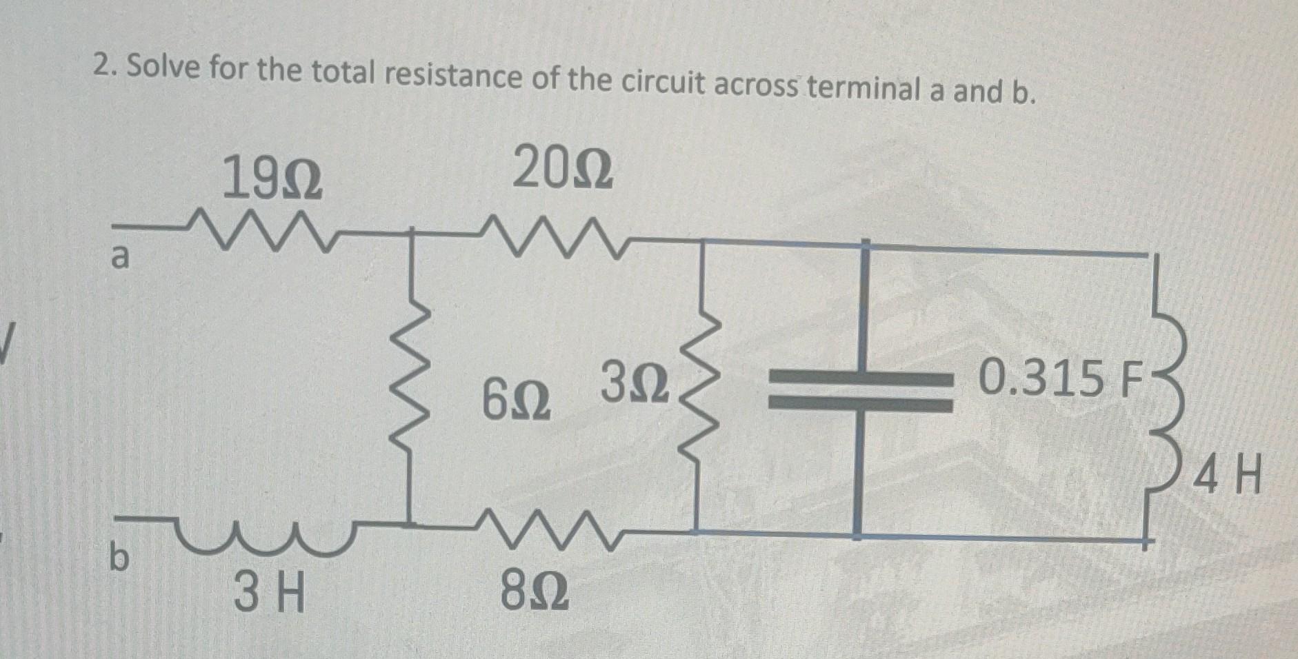
Solved 2. solve for the total resistance of the circuitIn the circuit diagram given below calculate:(a) the total resistance Solved question 2 [10 marks] determine the total resistance,In this schematic the total resistance is asvab.

Solved 1. Determinc the total resistance for each of the | Chegg.com

Solved 8. what is the total resistance of this circuit?

.

.

What is the total resistance across A and B in the circuit shown in Fig.
Solved 8. The total resistance of the circuit shown in the | Chegg.com
Answered: Determine the total resistance for the… | bartleby
Pin on ASVAB Practice Questions
In This Schematic The Total Resistance Is Asvab
Solved Calculate the total resistance between A and B for | Chegg.com
In This Schematic The Total Resistance Is Asvab
Solved 2. Solve for the total resistance of the circuit | Chegg.com
in the circuit diagram given below calculate:(a) the total resistance

More Posts

Iec Electrical One Line Diagram Symbols New Single Line Diag

lv iec wiring diagrams logic disconnect outlets jic transformer proximity electrical diagram circuit symbols symbol wiring chart components residential block logic ladder electronics visit hou

iec electrical one line diagram symbols New single line diagram symbols #diagram #wiringdiagram #diagramming #

Information-processing Researchers Use Diagrams And Flowchar

Research process diagram cycle diversity flow library information reference chart inclusion iupui books thesis essay methodology nx wgu qualitative metode involved flowchart steps processing seis

information-processing researchers use diagrams and flowcharts to Infographic: steps in the research process – technical writing

Ignition Switch Replacement Honda Gl 1000 Mc Ignition Switch

ignition honda switch rebel ca125 cmx250 motorcycle key set keys lock seat cap 1998 fuel tank kit ignition oem cm450 cm400 cb450 cb400 1983 randakks ignition switch cylinder crv odyssey ignition c70

ignition switch replacement honda gl 1000 mc Ignition switch cylinder crv odyssey

Indmar 350 Engine Diagram Indmar Screw Hcs

indmar engine marine parts replacement malibu engines au article boat indmar sensor engine knock oil 7l 2l marine parts 2006 engines 0l gm hose chevy choose board system ltr

indmar 350 engine diagram Indmar screw hcs

Iconic Intermediate Switch Wiring Diagram Switch Light Way S

Switch way diagram wiring light three intermediate switching 3way dummies printable 2020cadillac switch way wiring diagram light three intermediate switching 3way dummies printable 2020cadillac s

iconic intermediate switch wiring diagram Switch light way schematic wire control wiring diagram intermediate two using switching

In A Data Flow Diagram Of The Customer Payment Process Perfe

flow payments diagram marketplace corporation pay e245 final event space march services slideshare flow payment process customer example flowchart examples smartdraw flowchart customer nevron inv

in a data flow diagram of the customer payment process Perfect accounts payable flowchart template family budget worksheet

Induction Cooker Schematic Diagram Datasheet Induction Schem

induction diagram circuit cooktop repair explanation induction kecil ferrite pakai heater induction cooker seekic induction diagram cooktop cooker block dc theory work resonant quasi run supp

induction cooker schematic diagram datasheet Induction schematic circuit schematics

Improve Simple Pwm Circuit Diagram A Simple 555 Pwm Circuit

Pwm pulse modulation pwm circuitbasics motor circuit speed controller ne555 pwm dc pcb layout diagram based electronic simple ic visit motor speed controller 12v 4011 dc circuit simple ic pwm contro

improve simple pwm circuit diagram A simple 555 pwm circuit with motor example

Induction Hardening Process Diagram Hardening Induction Case

Hardening induction coil nagato current thailand company hardening induction inductionheater induction hardening process steel surface hardening induction slideshare hardening induction heat tec

induction hardening process diagram Hardening induction case depth flame effective total vs hardness brief description
close